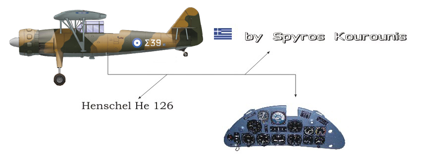
Henschel Hs 126
Hinweise von Spyros Kourounis
(in englischer Sprache)
Introduction:
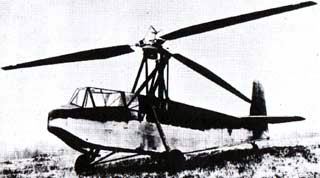
In 1933 the Luftwaffe issued a request for an advanced battlefield observation aircraft which would improve on the Heinkel He 46 (which had not then entered service). Henschel responded with the Hs 122, a neat parasol monoplane which offered an outstanding all-round view and excellent low-speed and short-field characteristics. The prototype flew in early 1935 powered by a Rolls-Royce Kestrel, although the Siemens Sh 22B radial was the intended motorplant. Flight tests were successful, but the Luftwaffe was disappointed with the maximum speed, which was little better than the He 46. Therefore, Henschel was asked to further develop the aircraft using the Bramo 323 Fafnir radial. This design became then the well known Hs 126.
Henschel took the opportunity to revise the design, with a longer fuselage, more angular wing layout and also refinements to the vertical tail and cantilever undercarriage.
Flight trials revealed excellent short-field capability and easy handling. A pre-production batch of 10 Hs 126A-0s was completed, some of which were issued to reconnaissance squadrons for evaluation. The first production aircraft were delivered in early 1938. These Hs 126A-ls switched to the BMW 132Dc engine to overcome the non-availability of the Fafnir. The cockpit accommodated the pilot and a gunner/observer, both provided with a sliding canopy. The back-seater operated a Zeiss Rb topographic camera in a bay behind him, a hand-held camera and the 7.9-mm MG 15 machine-gun with 975 drum-held rounds. The pilot aimed the fixed MG 17 machine-gun with a capacity of 500 rounds, mounted in the upper starboard fuselage. For light bombing missions the aircraft could carry five 10-kg (22-lb) bombs in the camera bay and a single 50-kg (110-lb) bomb on a port-side strut which was braced to the wing and the fuselage.
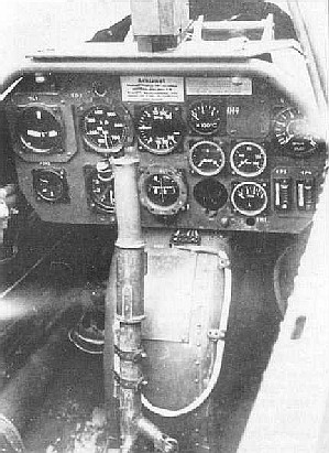
Henschel Hs 126-K6
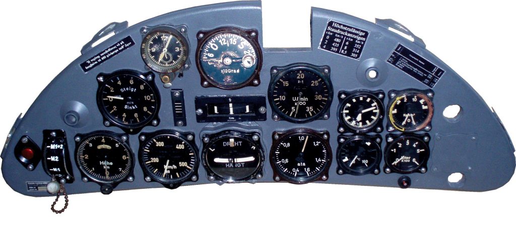
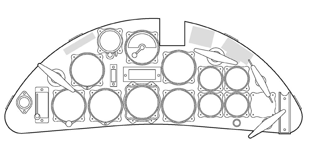
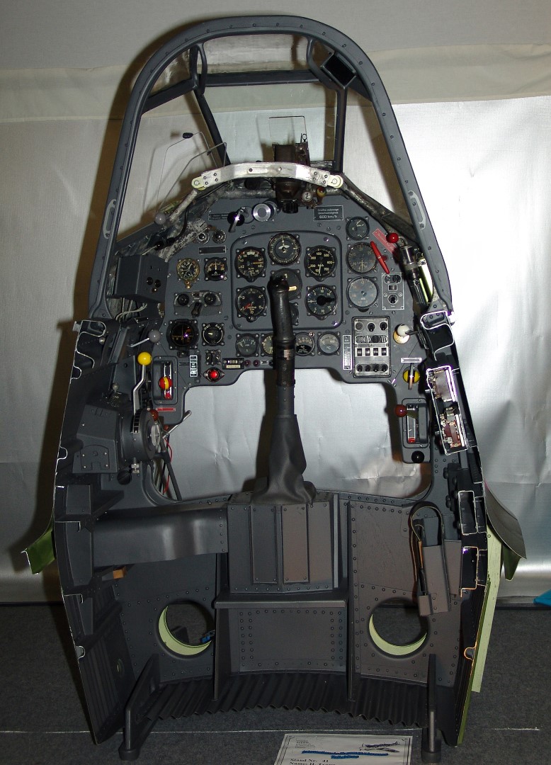
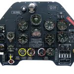
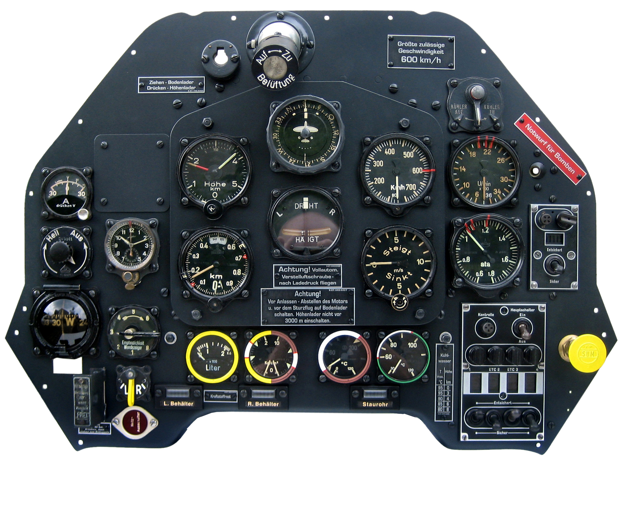
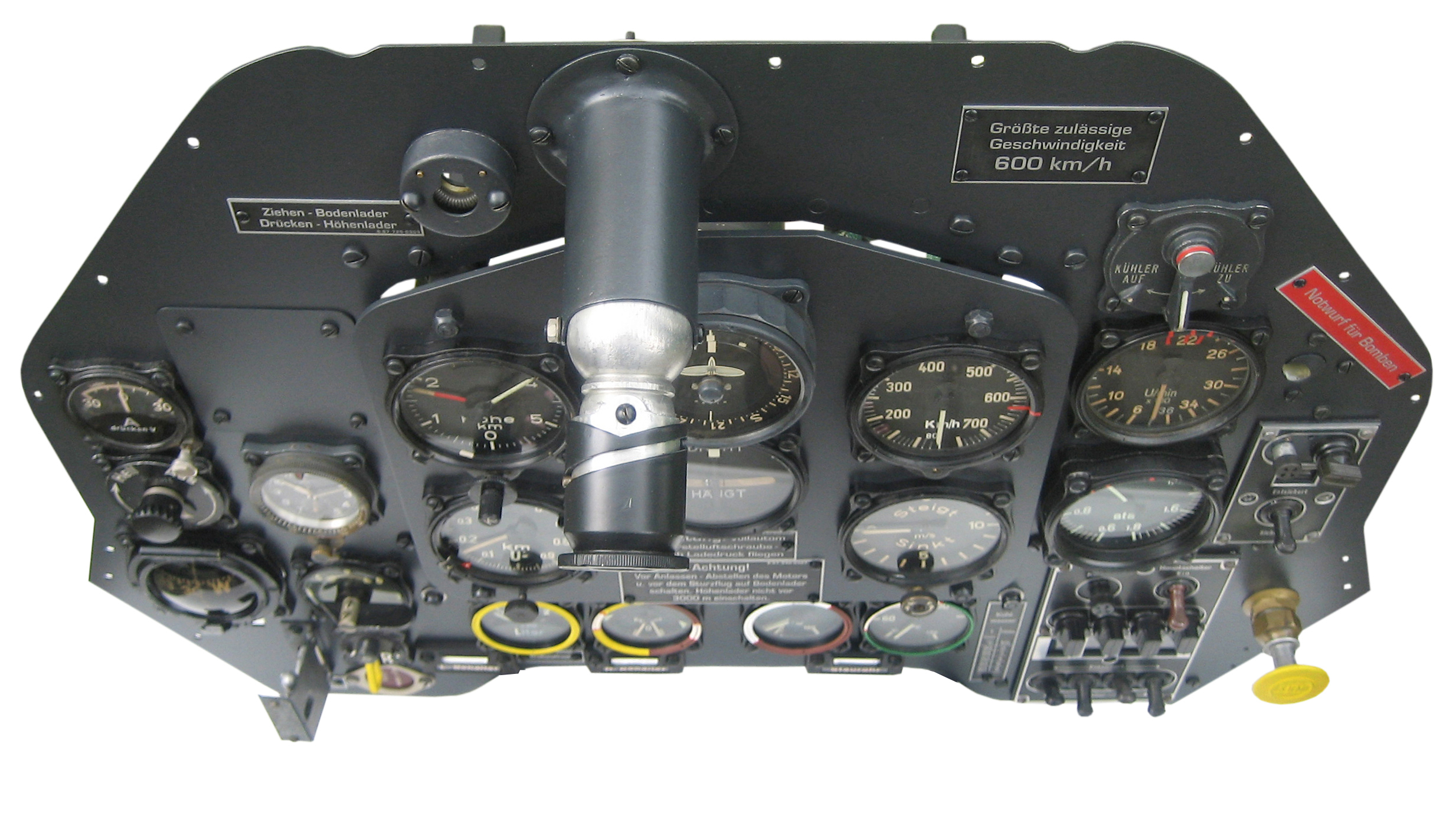
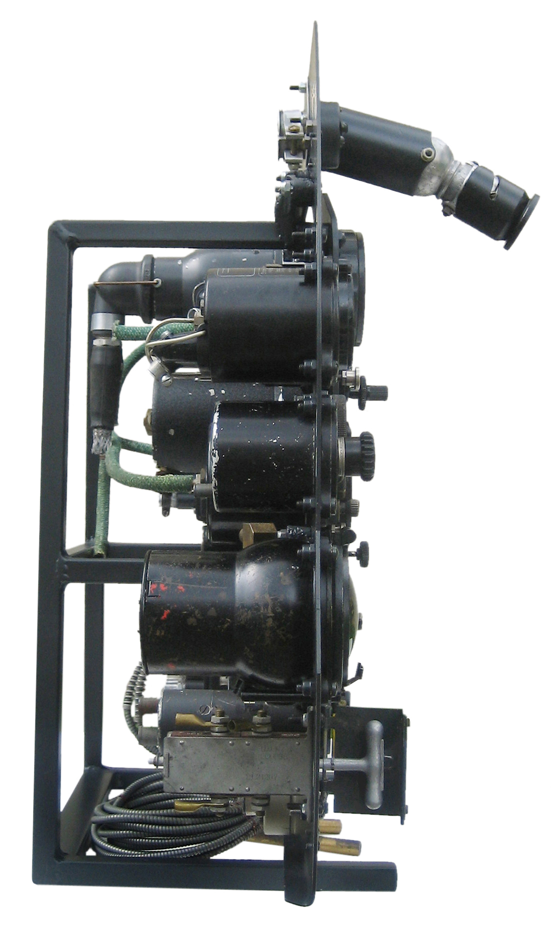
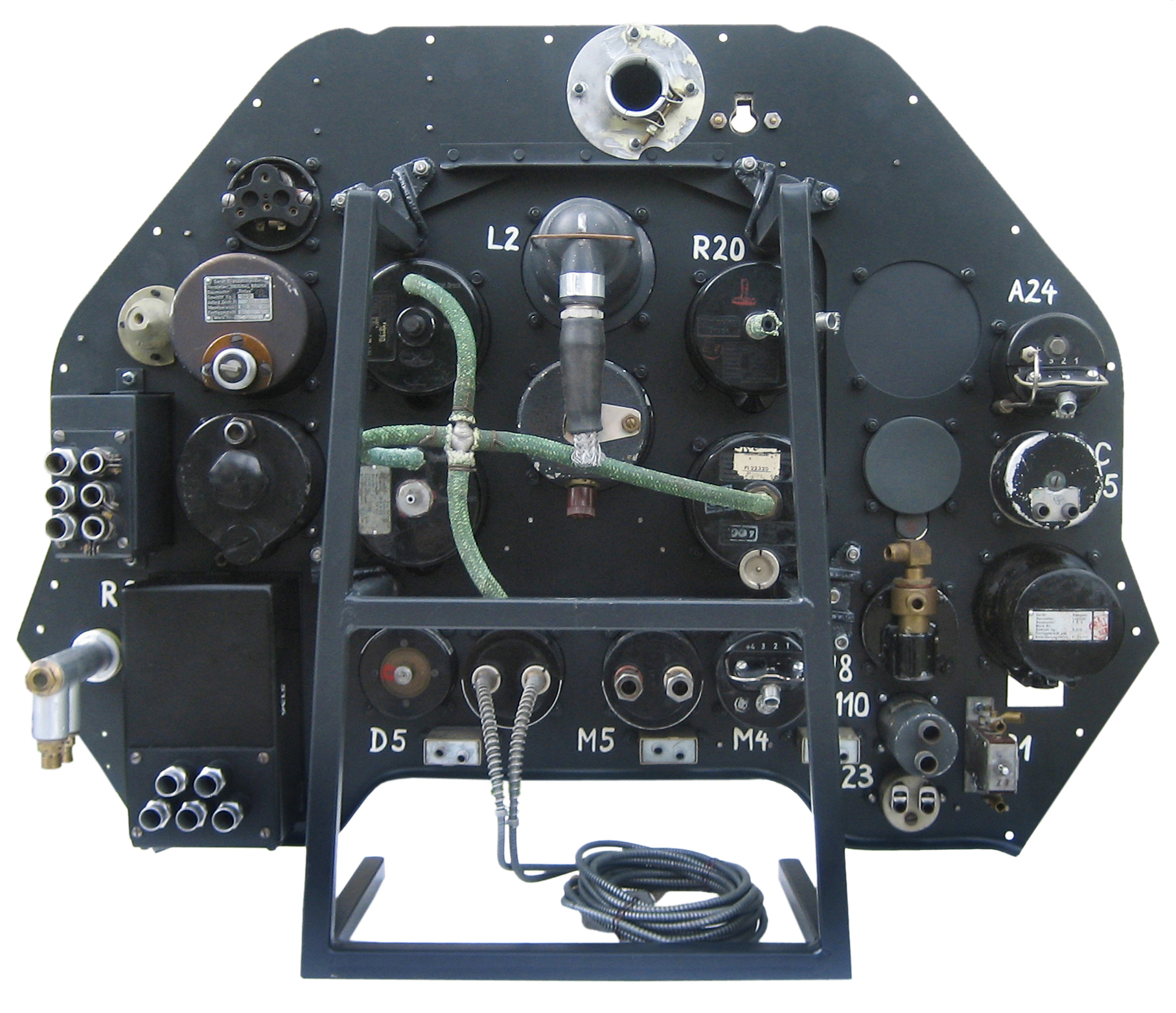
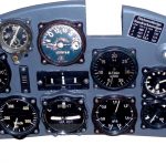
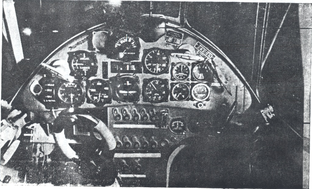
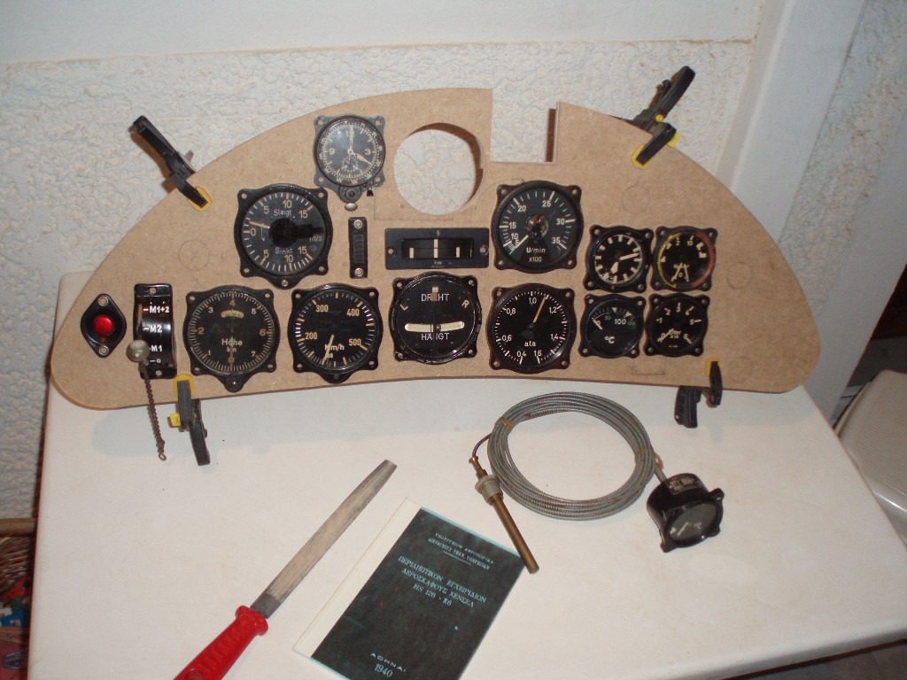
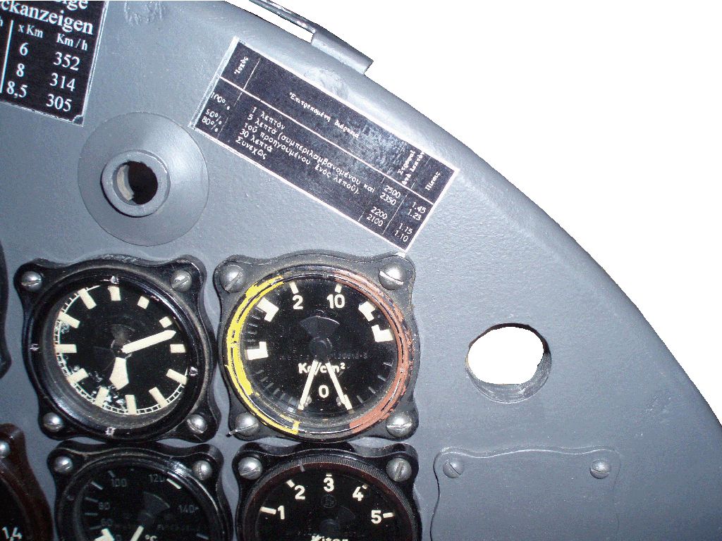
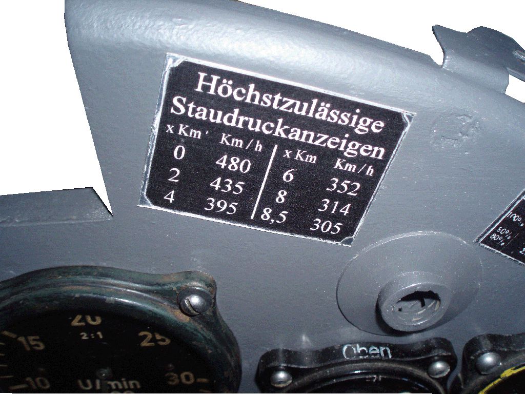
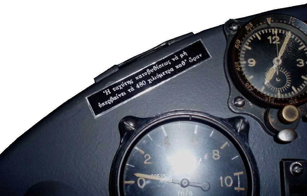
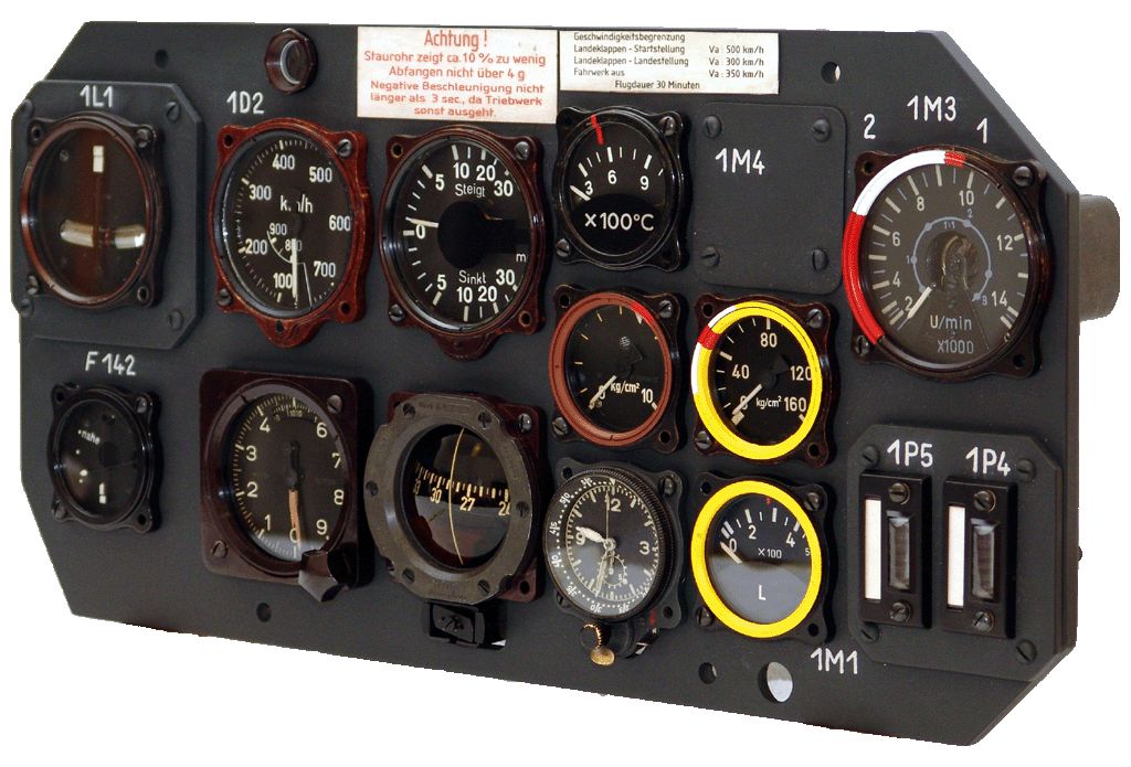
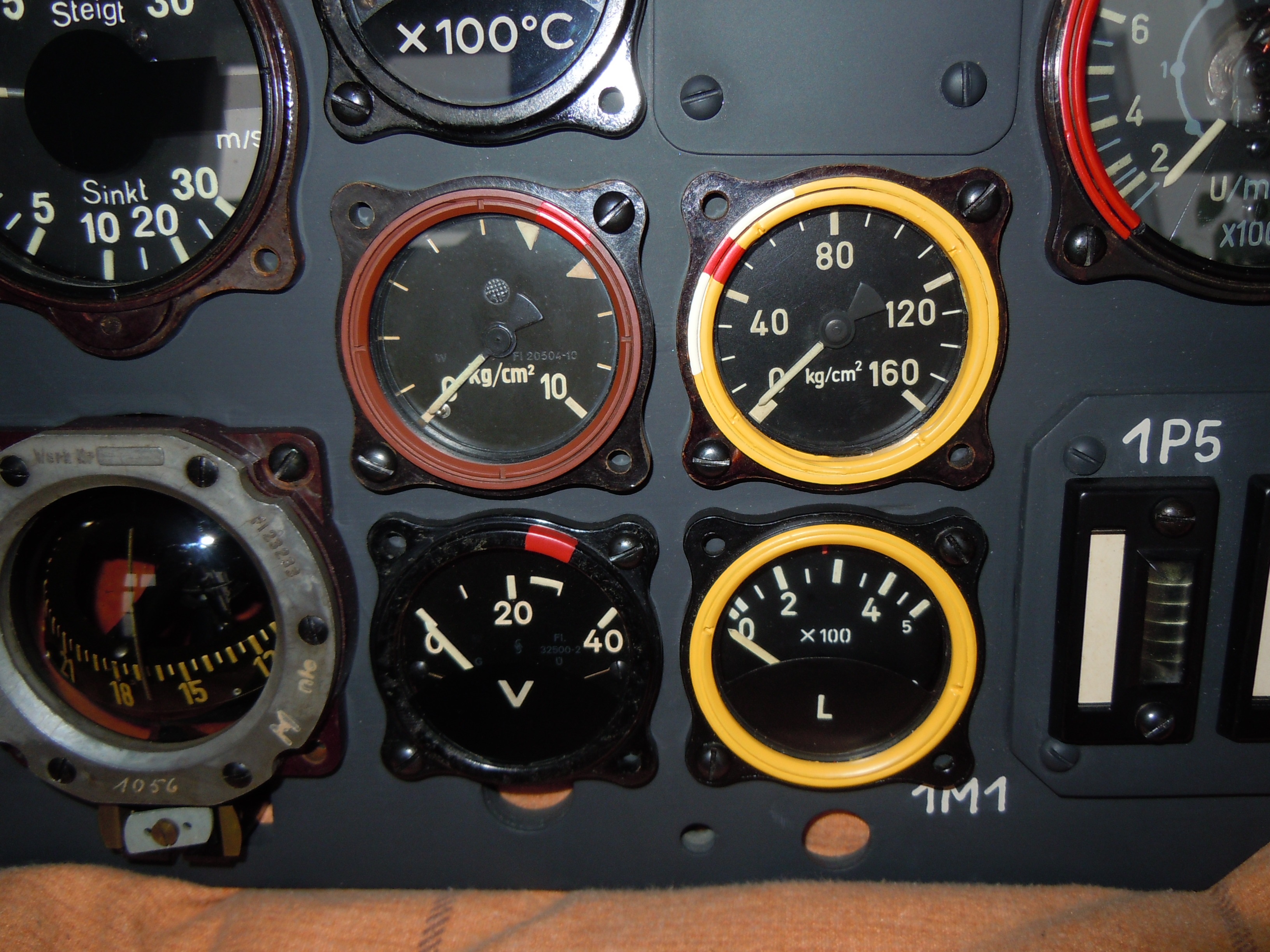
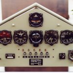
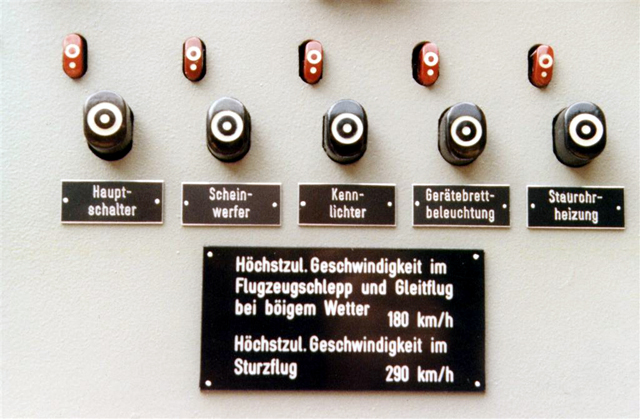
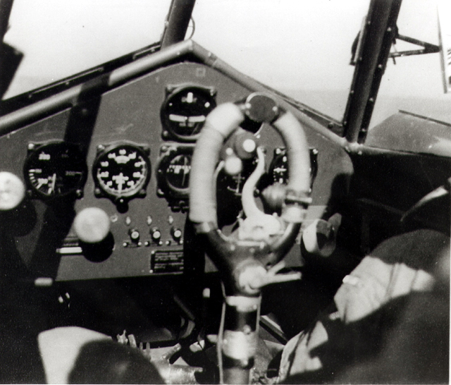
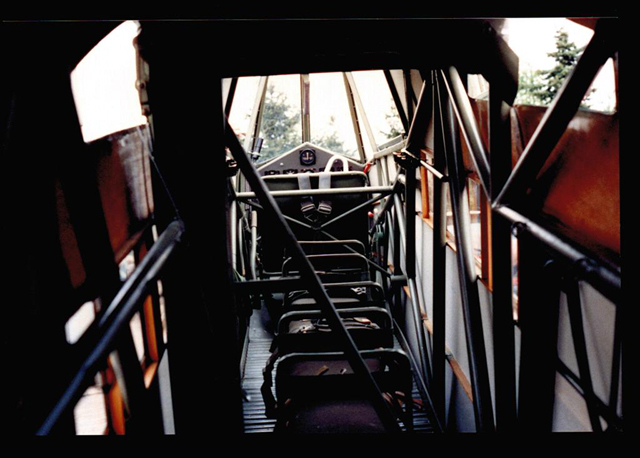
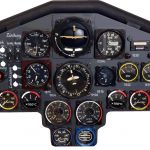
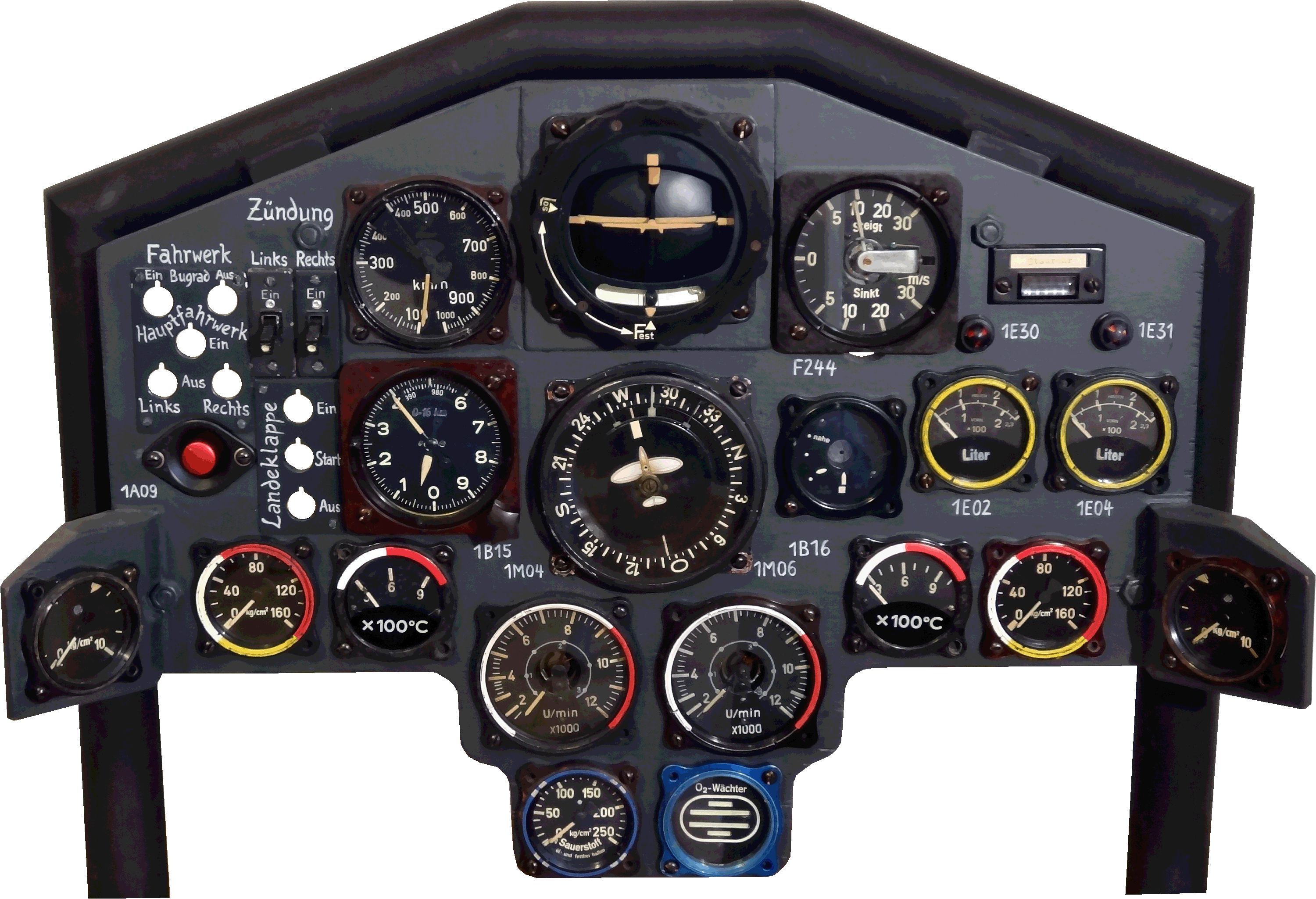
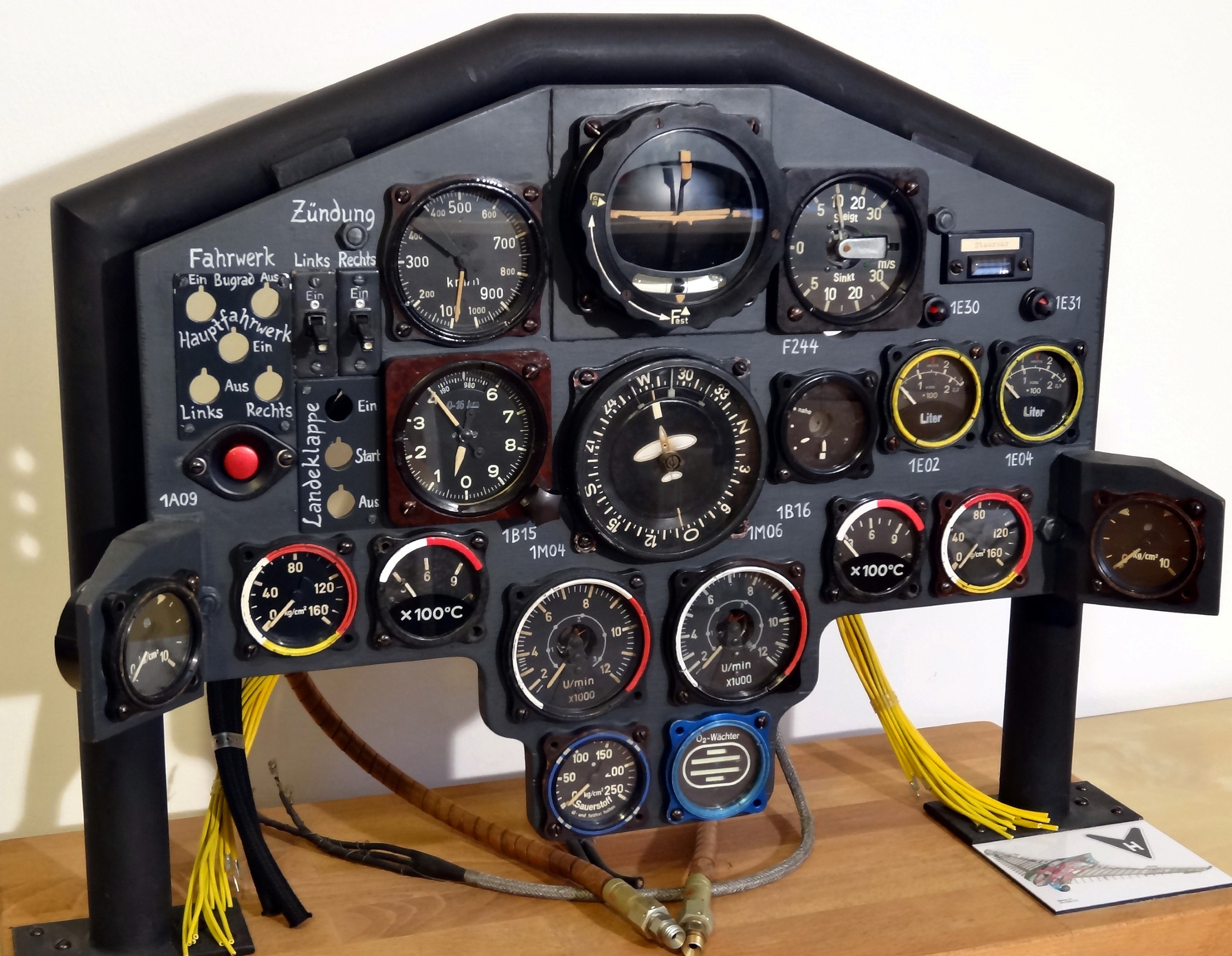
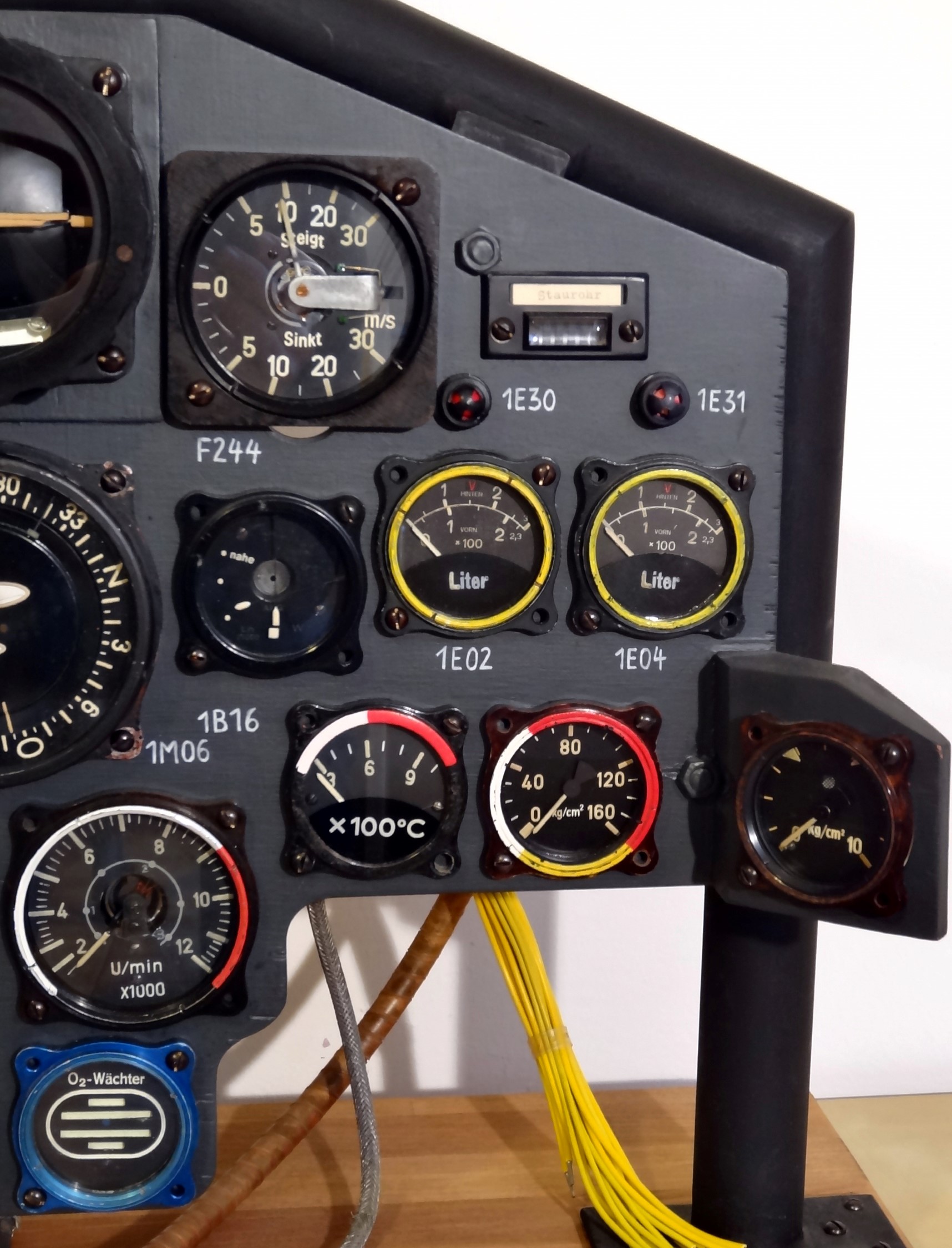
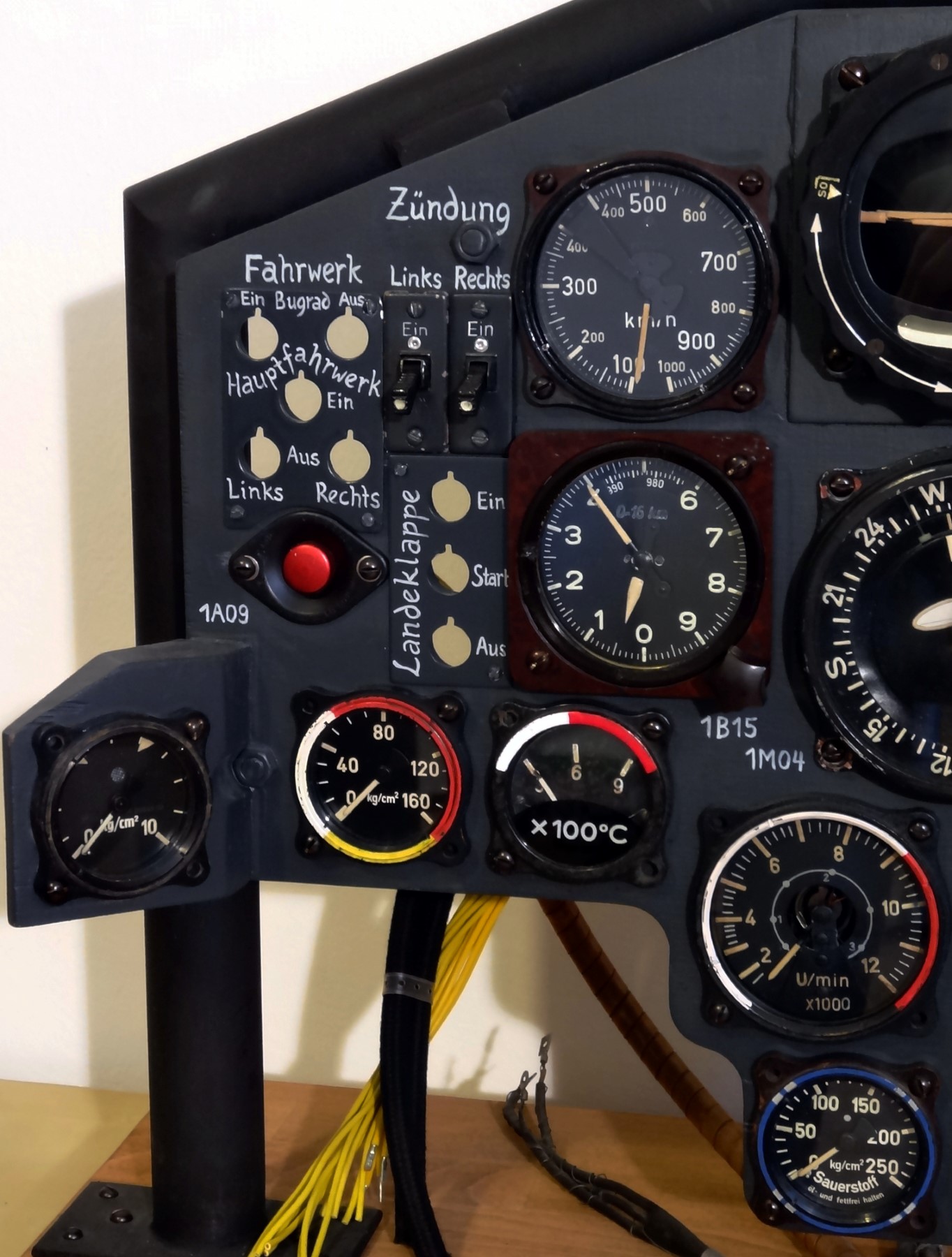
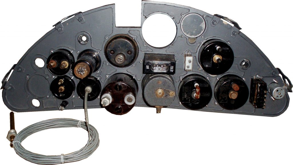
 The Hs126’s instrument panel:
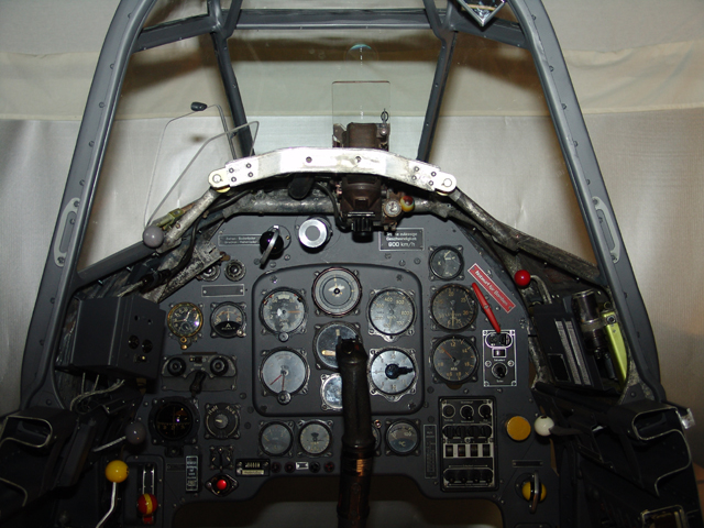
The Henschel Hs126s instrument panel had many differences according to the standard types of the aircraft (A or B) used by the Luftwaffe.
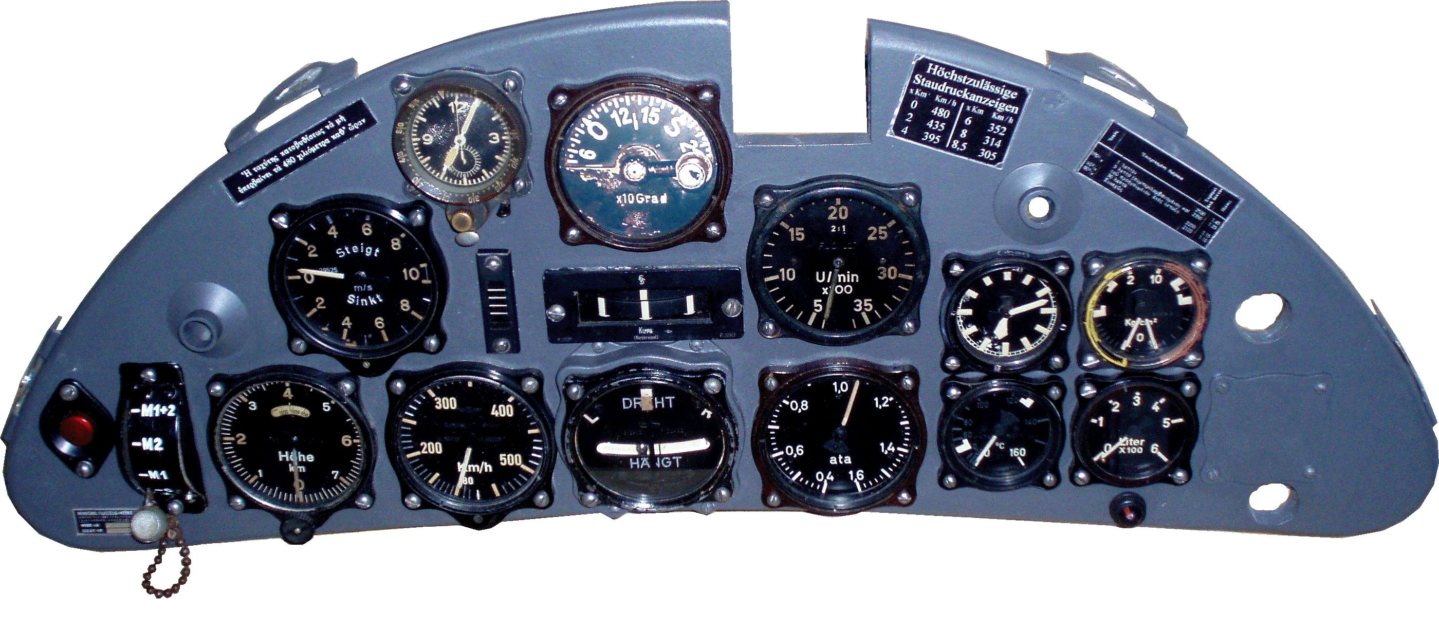
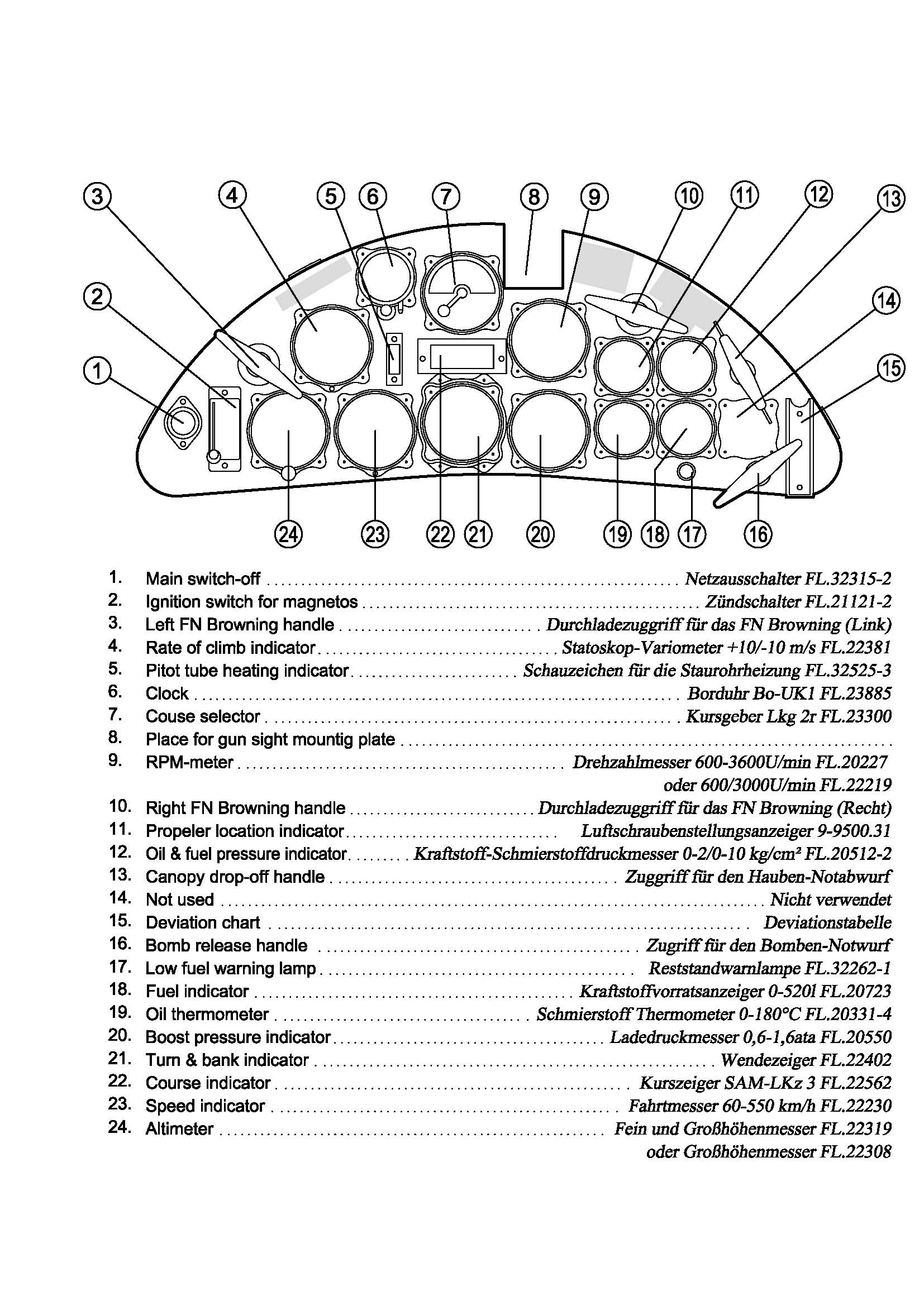
The instrument layout of the Greek Hs126s (type K) panel was neither the standard of the Hs 126A-1s nor that of the Hs 126B-ls. It was similar to the Hs126B but it had two very interesting details:
– The Tochterkompass was not installed
– There was a second machinegun handle for the additional front Browning machinegun at the upper left side above the Variometer.
Also, as stated before, there was a simple ring-and-bead sight installed, instead of the Luftwaffe’s standard Reflexvisier Revi 12B.
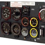
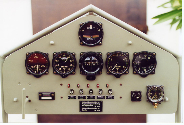
The instruments of this panel are as shown by the photo below!
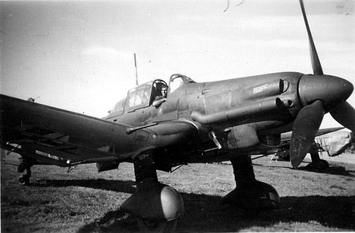
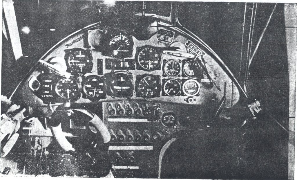
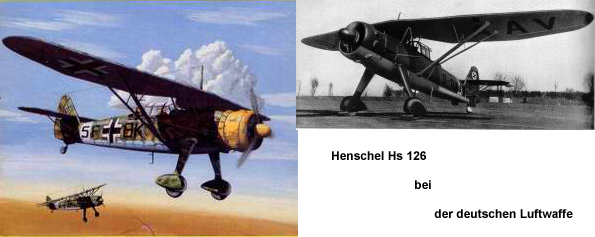
Henschel He 126 – Type K
Henschel Hs126 in action:
Six Hs 126A-ls were sent to Spain in 1938 for combat evaluation with the Legion Condor. There they proved very successful in both the light bombing and reconnaissance roles. The five survivors remained in Spain after the end of the Civil War, and a further 16 were exported to Greece. By September 1939, Hs 126 production was in full swing, and soon the Hs 126B-1 was available, powered by the originally intended Fafnir 323 radial, offering better performance. Radio equipment was also upgraded, with the FuG 17 VHF set as standard. Thirteen reconnaissance squadrons of Hs 126s took part in the Polish campaign in September 1939. In addition to their traditional roles of army cooperation, battlefield reconnaissance and artillery spotting, they also strafed and bombed Polish positions. In the absence of effective air defense, the Hs 126 could operate with relative impunity.
Hs 126s were next in action over France, performing reconnaissance missions along the Maginot Line in late 1939. However, by the time the Luftwaffe turned on France in earnest, in May 1940, the Hs 126 was beginning to prove easy meat for fighters. Production of the aircraft slowed dramatically with the decision to procure the Fw 189 for the battlefield reconnaissance role, and the last aircraft was delivered in January 1941.
While the Aufklärungsstaffel (H) waited for the Fw 189, the Hs126s flew in North Africa, and the Russian front. After the re-equipment with newer types from the spring of 1942, the displaced Hs 126s relegated to second-line duties. Among these was the towing of DFS 230 gliders. From the autumn of 1942, a handful was used as night harassment aircraft by the Nachtschlachtgruppen. Two such units operated in the Balkans, operating a few examples of the aircraft right until the last days of the war.
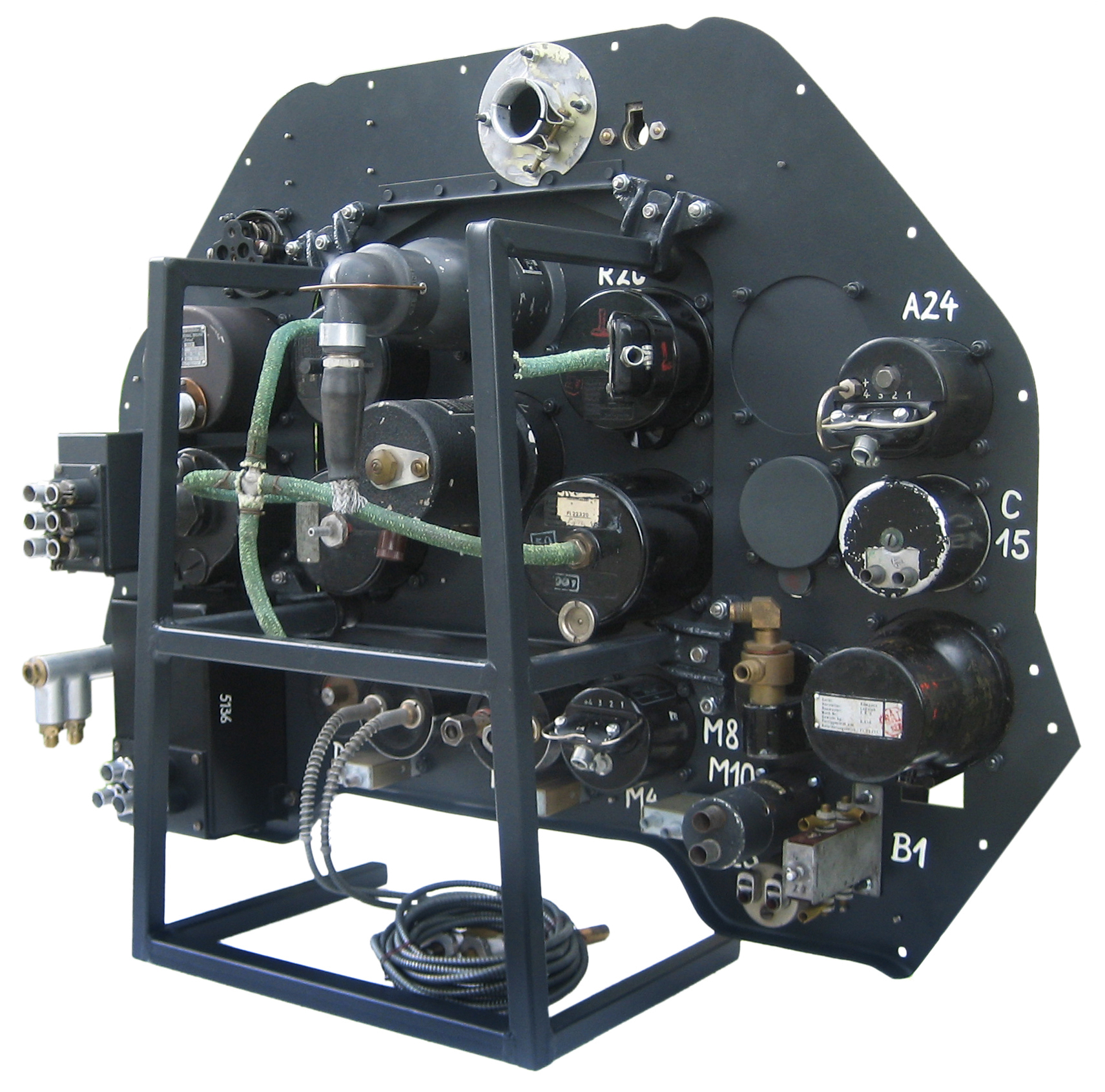
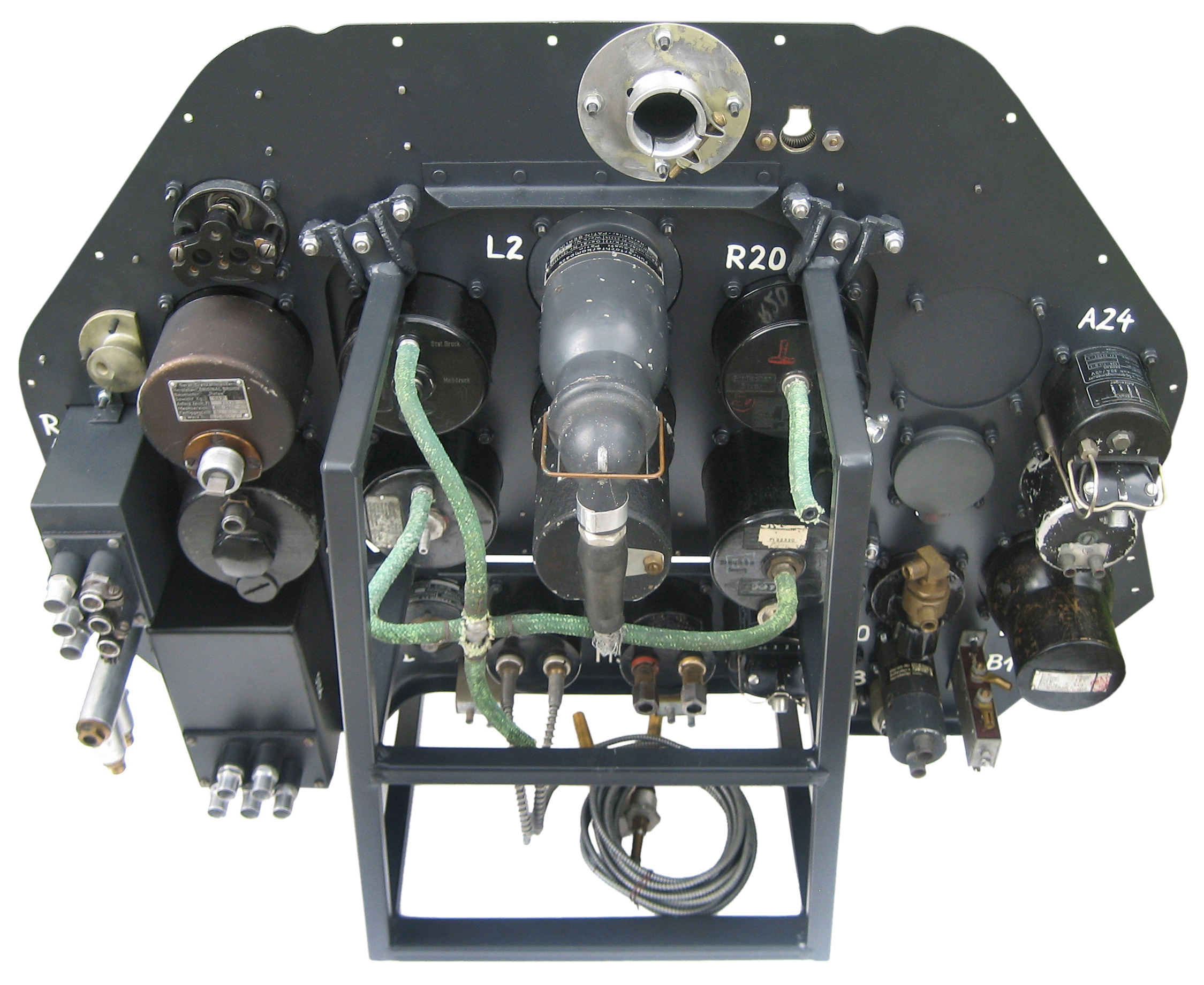
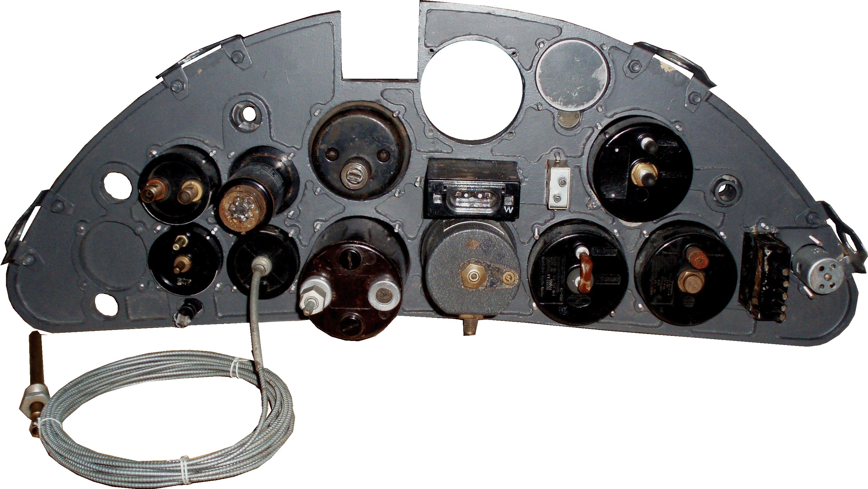
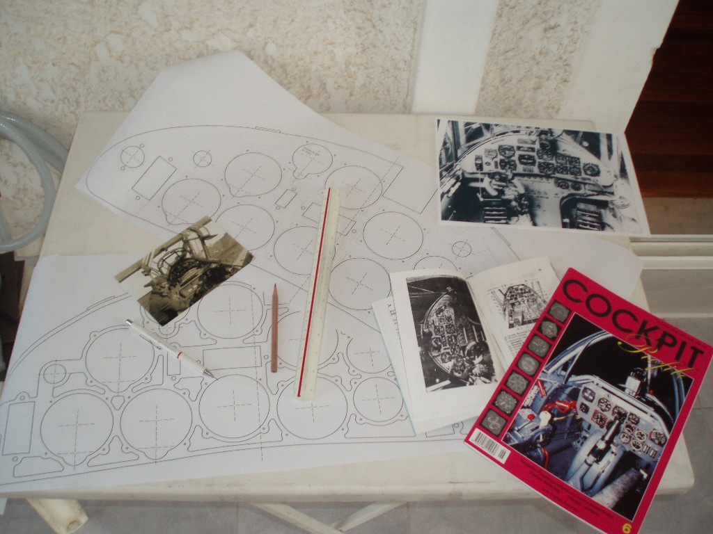
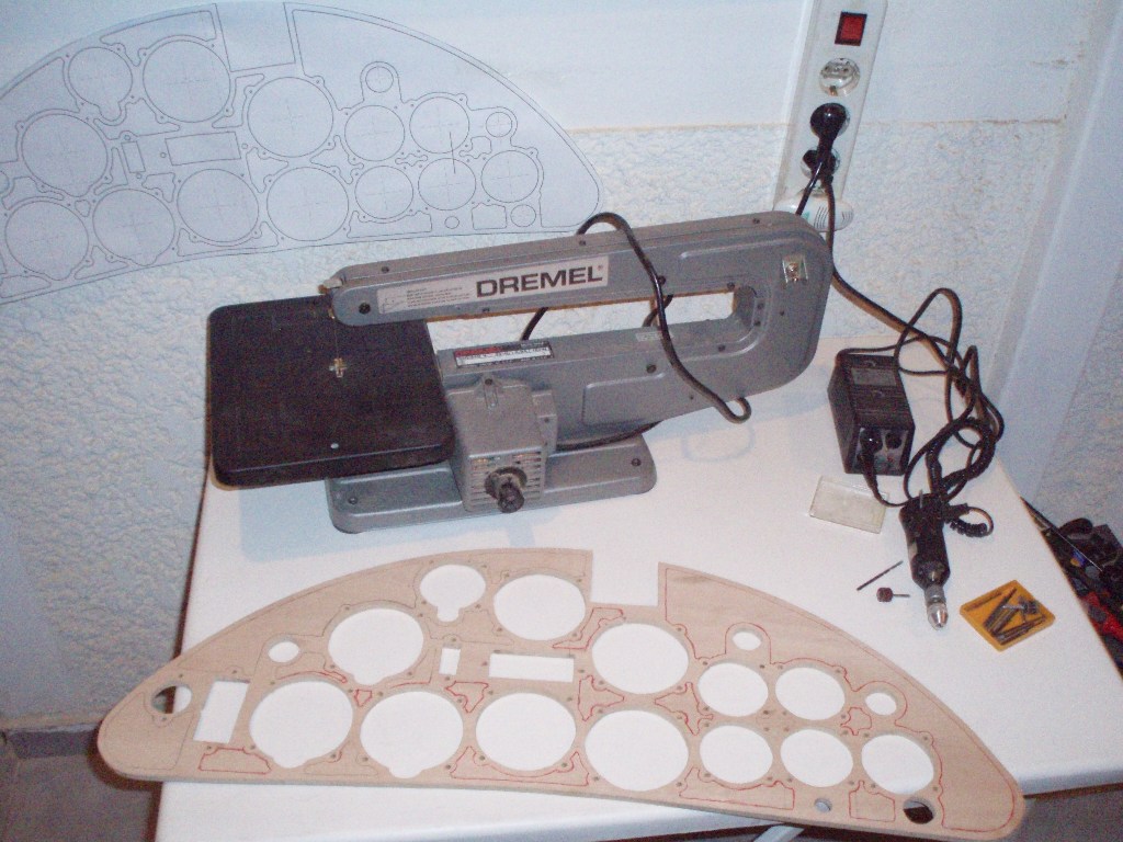
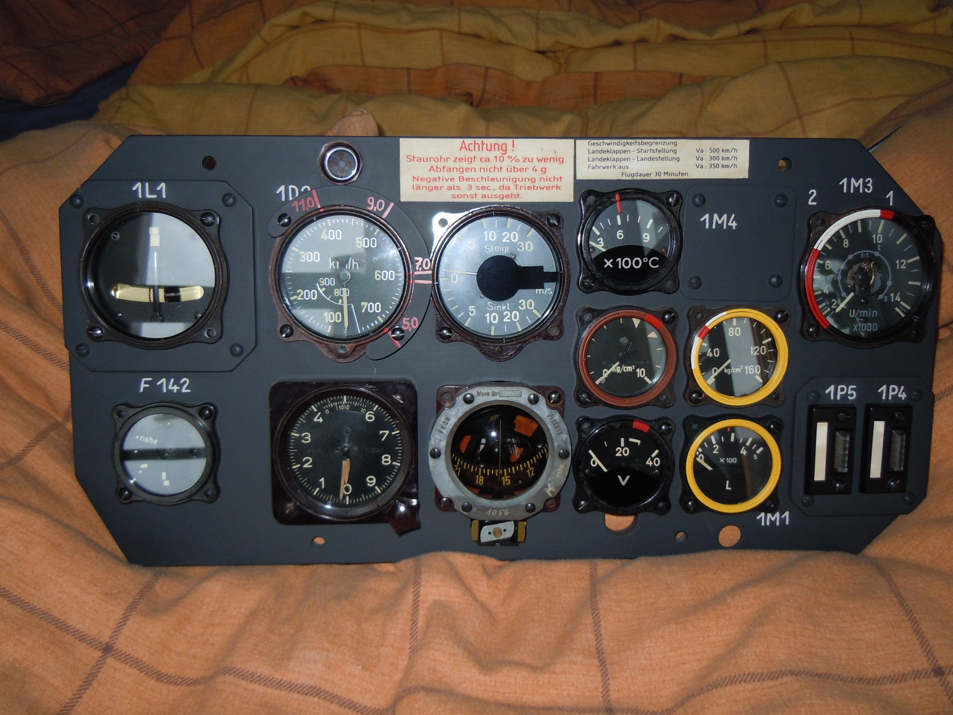
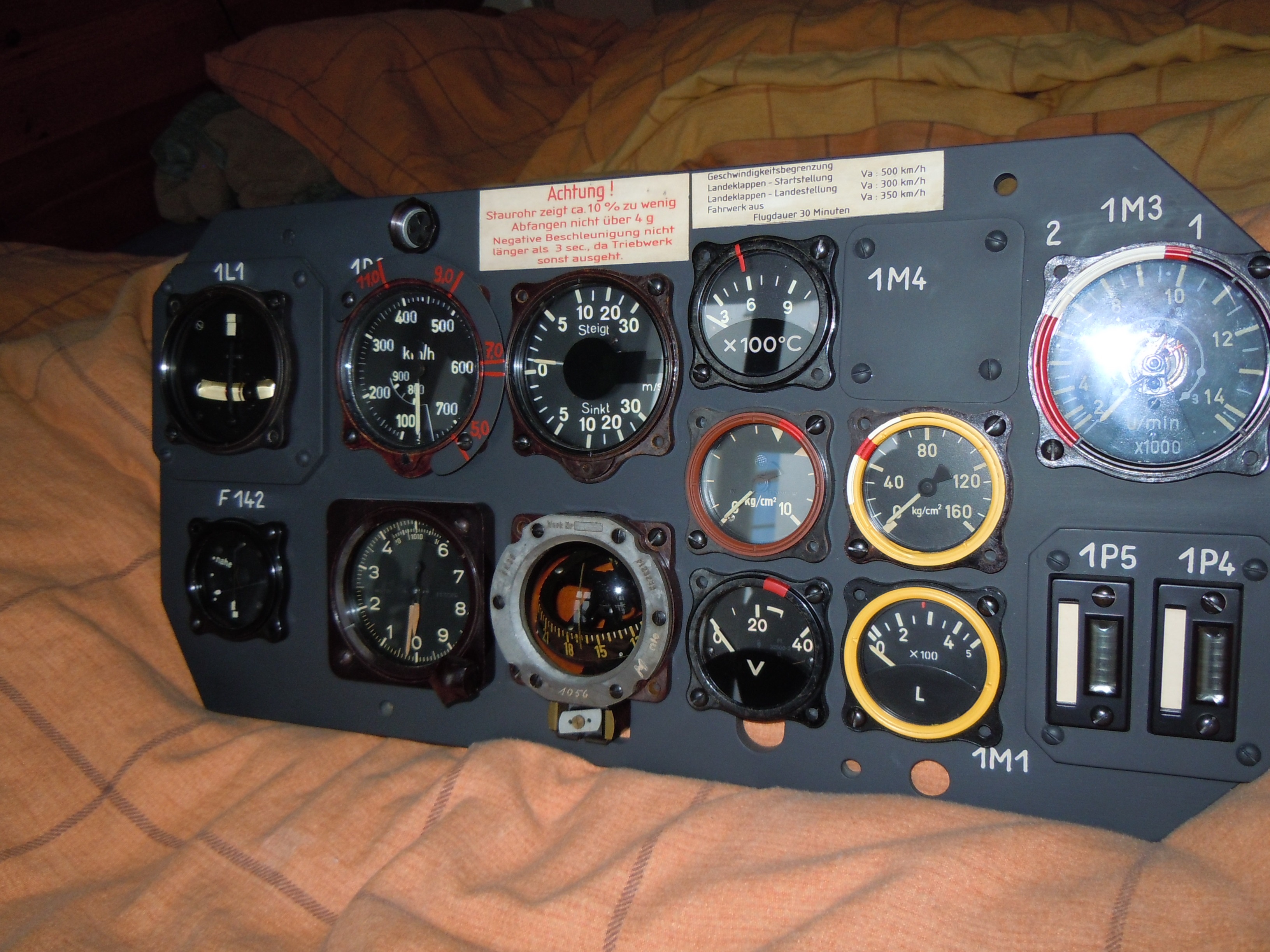
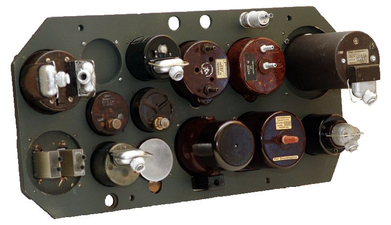
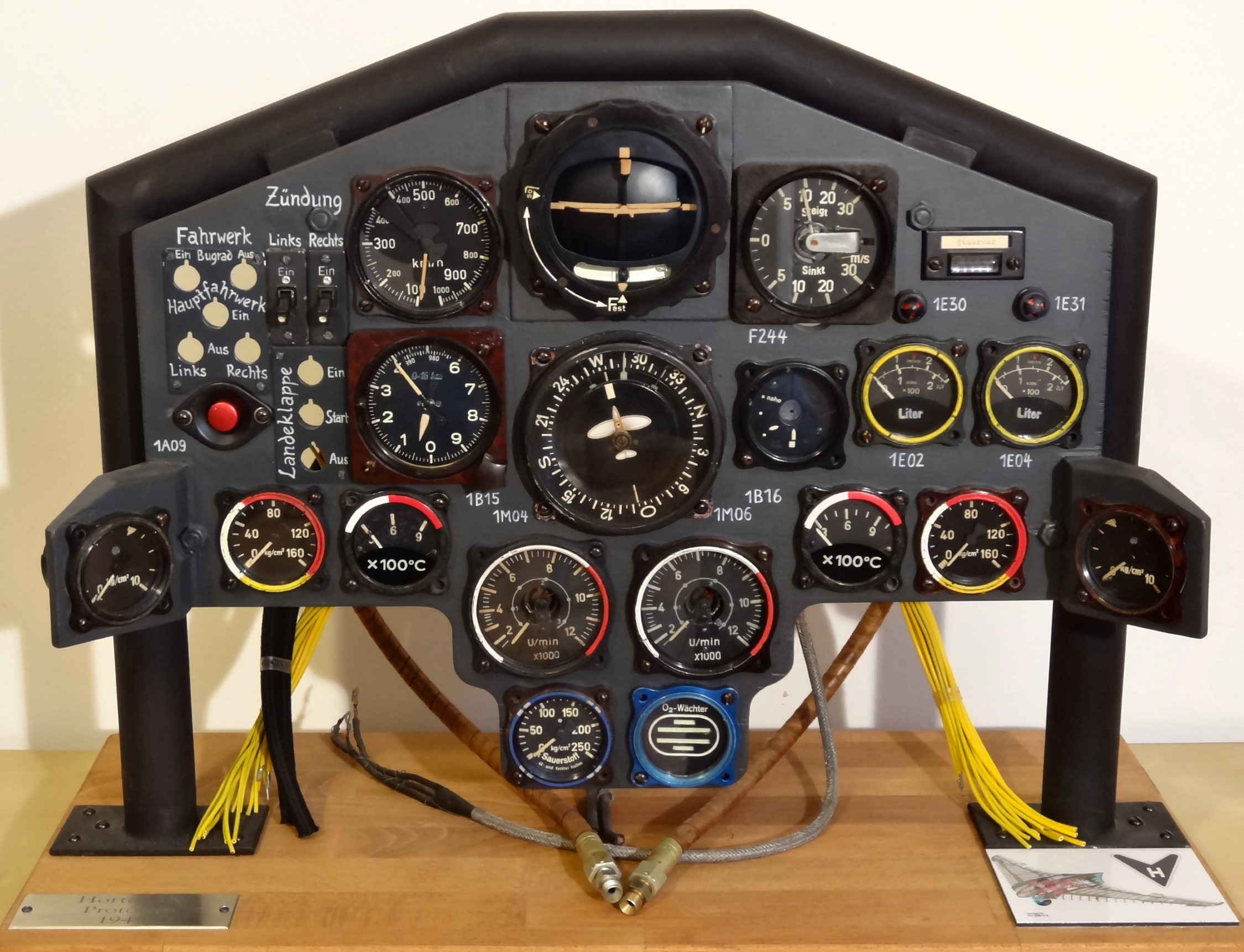
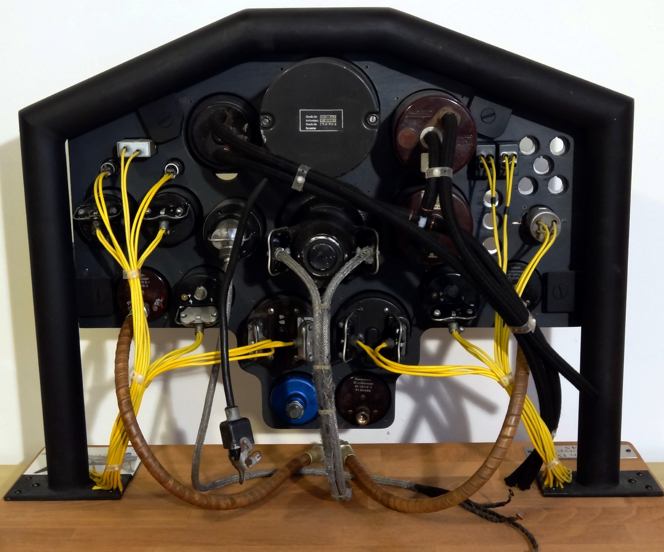
The construction of the instrument panel:
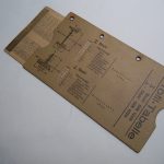
The only available information concerning the reproduction of the panel was some photographs from the Greek flight manual (Henschel Hs126-K6 Betriebsanleitung) and a batch of images and diagrams from various publications. Since there was no drawing, I used these photographs and with the help of photogrammetry, I designed the panel in detail.
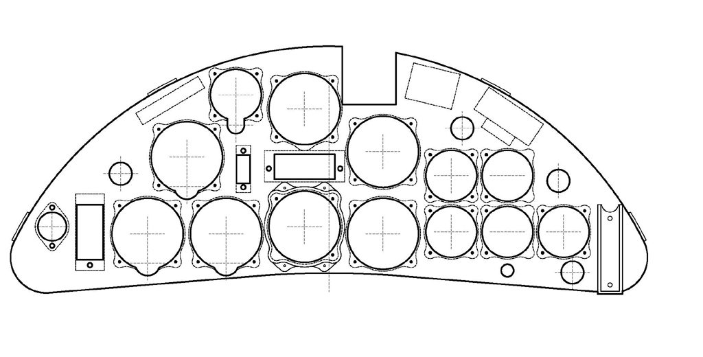
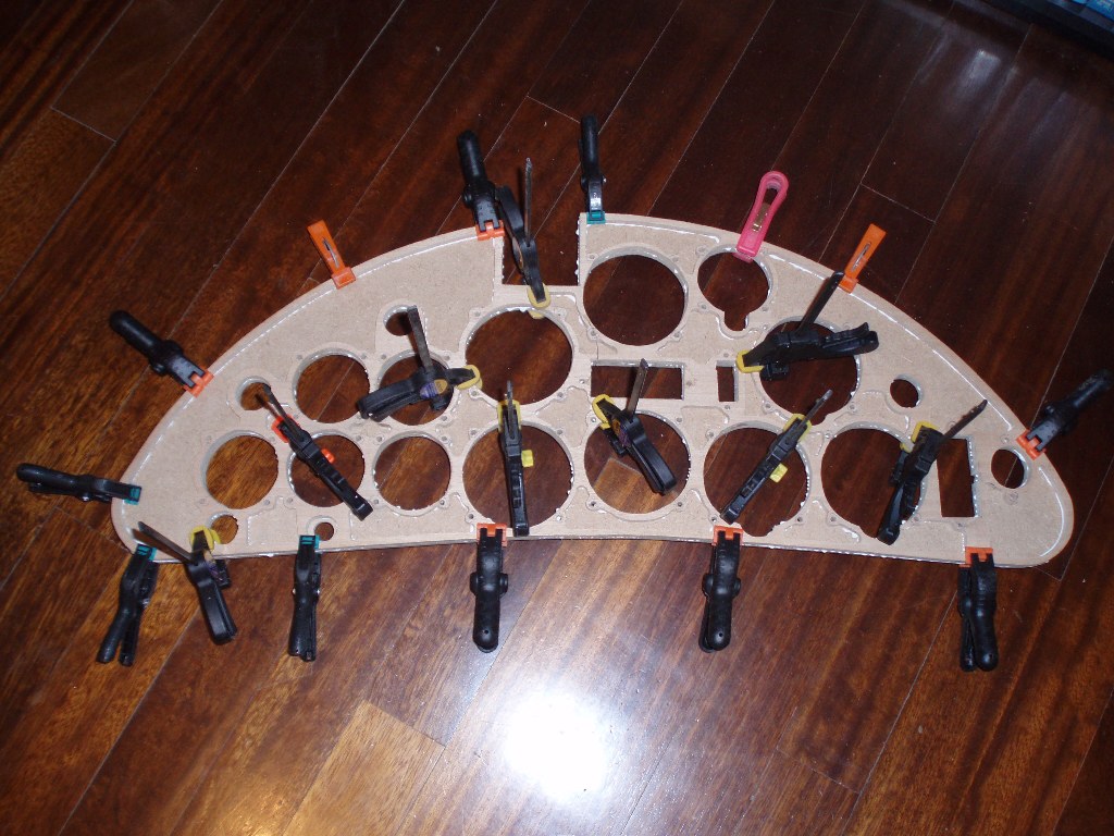
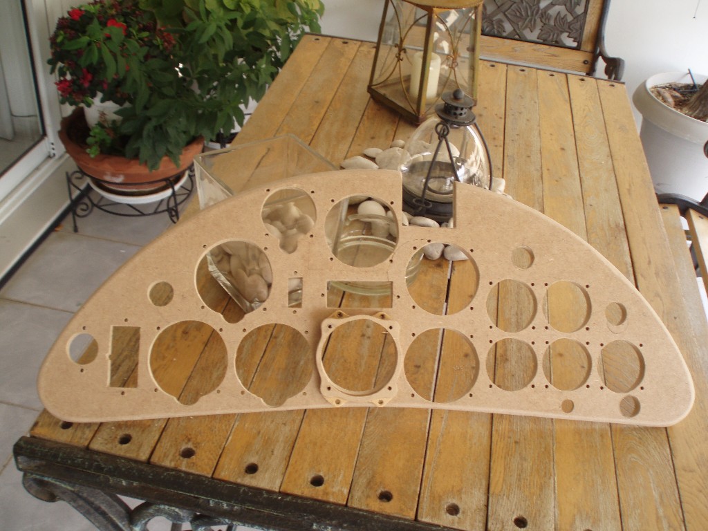
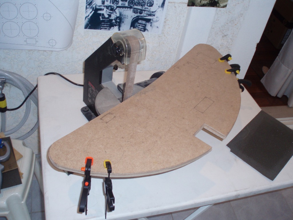
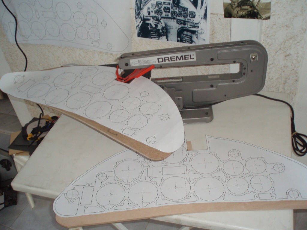
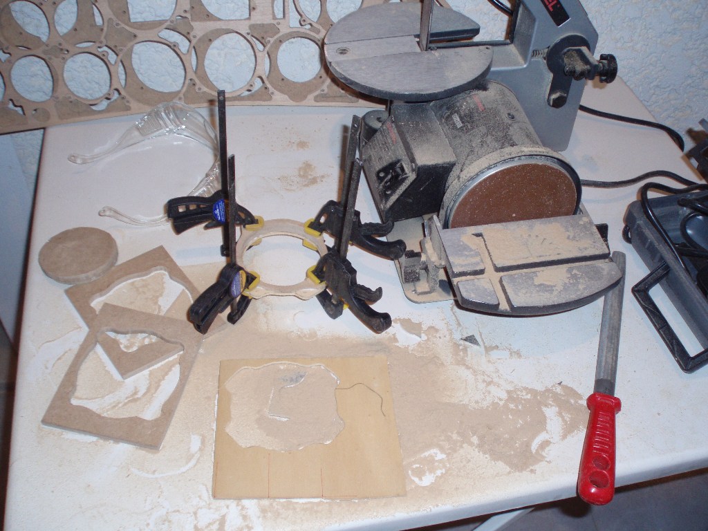
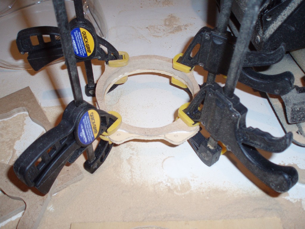
For the construction of the panel, MDF wood was selected, due to its high durability and homogeneity. The actual instrument panel was metallic from alloy with added reinforcements on the back side, where the instruments were installed. Trying to reproduce these reinforcements, I cut two identical wood surfaces, at the shape of the panel, each board having width of 7mm. The total width of 14mm allowed for the 1cm curding (curvature) of the panel, during the latter stages of the construction, so as to reproduce the metal curving of the actual panel. On the first wood board, the instruments holes and the bolting spots, were sketched and cut, while the back side reinforcements were sketched on the second wood board.
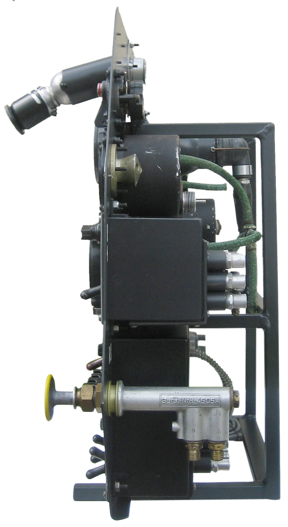
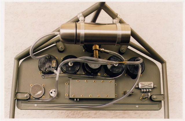
Before the curving of the panel, a check was made so as to verify the correct placement of the instruments.
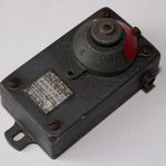
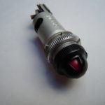
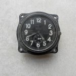
One of the most difficult tasks was the reproduction of the special mounting base of the turn and bank indicator (Wendezeiger Fl.22402) ensuring the horizontability of the instrument.
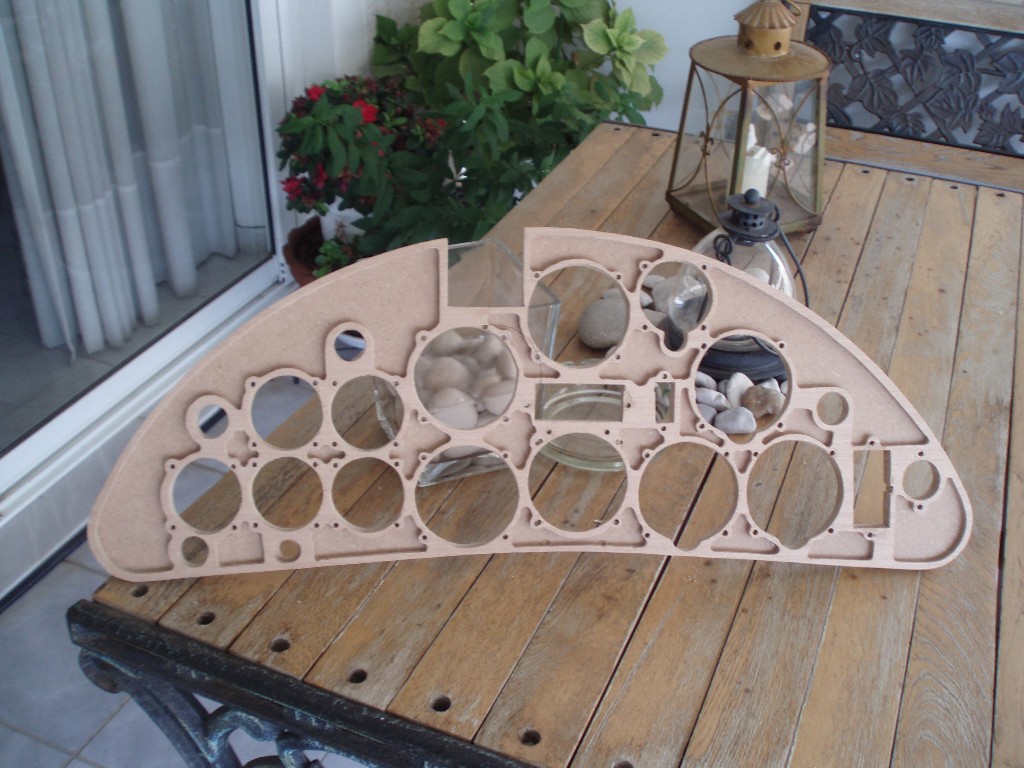
The construction of the panel was completed with the bolting of the said mounting base and some final refinements and fine sanding .
The finished panel was painted with the appropriate color, interior grey RLM 66 after primer varnish.
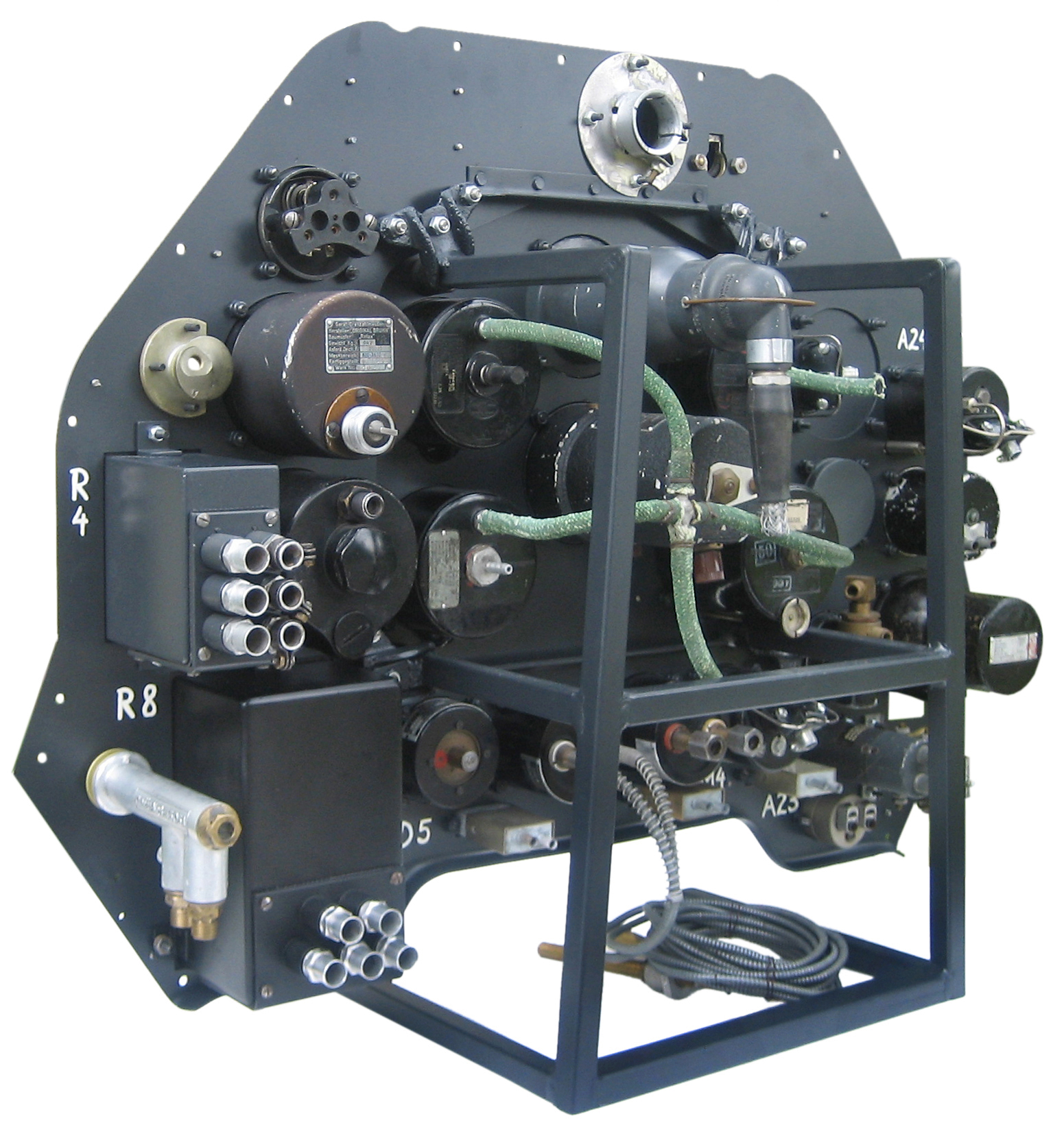
Steps by building the panel
The Greek Henschels:
The acquisition of Henschel Hs 126s to augment the obsolete Potez 25A2s and Breguet 19A2/B2s was apparently initiated in spring 1938. The Henschel Flugzeug-Werke A.G. was advised by the Reichsverband der Deutschen Luftfahrt-Industrie (RDLI) in July 1938 that the Greek air force was interested in their „multi-role aircraft“, whereupon Henschel made preparations to meet an order for 16 to 32 Hs 126s.
Greek officers visited the Henschel factory in Johannisthal and Schönefeld in November 1938, and one of them flew a Hs 126.
Subsequent negotiations for the purchase of 16 Hs 126s were promising, problems arising solely because the Greeks wanted to acquire a manufacturing license because they initially distrusted the fuel-injection radial engine, and because Britain was offering Westland Lysanders on credit.
The contract finally signed on 22 April 1939, covered the purchase, for approximately four million Reichsmark, of 16 export versions of the Henschel Hs 126 (type K) with five spare engines, maintenance equipment and 16 additional bomb installations, the delivery of which later was subsequently never requested. The contract made provision for possible follow-up sales and license manufacturing parts and materials.
The contract did not cover the mounting for the observer’s gun on each Hs 126 or various other items of equipment, which surely included the choice of the type of machine-gun the acquisition of these being left to the purchaser.
A Greek acceptance commission started work at Schönefeld in June 1939, Athens having meanwhile expressed a wish to purchase further aircraft.
When war broke out on September 1, 1939, construction of the 16 export-version Hs 126-Ks had been almost completed, and Greek ferry pilots arrived in late November. However delivery by air to Tatoi aerodrome at Athens was difficult due to bad weather and the first 10 Hs 126-Ks were only able to take off, in two groups early on December. The last of the 16 Hs 126-Ks arrived at Athens on February 7, 1940.
Greece subsequently sought to purchase further aircraft as Italy adopted an increasingly threatening posture towards Greece, but in May 1940, when the Wehrmacht launched its successful assault on France, the Reichsluftfahrtministerium(RLM) embargoed the export of aircraft.
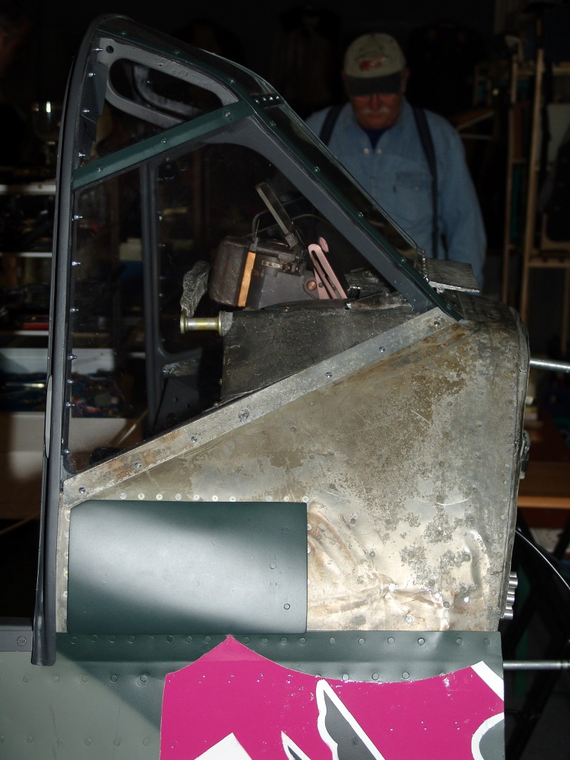
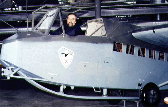
The suffix „K“ (Kampf, i.e. combat) appended to the designation of the Hs 126s delivered to Greece, also indicates they were neither standard Hs 126A-1 nor Hs 126B-ls, that some items of equipment were not identical with those fitted on the Luftwaffe versions and/or that modifications had been specified by the Royal Hellenic Air Force (RHAF). It was powered by the Bramo 323A-2, driving a VDM 9-11240 VI propeller, had Hs 126B-1 main landing gear, and the radio equipment was downgraded compared with that used by the Luftwaffe. The armament comprised two asymmetrically mounted 7.92 mm FN Browning for the pilot and a similar gun on a flexible mounting for the observer. There were twin tear-shaped blister fairings on the access panels immediately in front of the windshield to house the bulkier FN Browning breeches and the pilot was provided with an old-fashioned gun sight instead of the Luftwaffe Reflexvisier. Locally manufactured „American-type“ 50 kg and 14 kg bombs were carried on racks of RHAF design fitted under the fuselage just behind the landing gear, under the pilot’s cockpit and in the bay behind the observer’s cockpit.
The Greek Henschels in action:
On 28 October 1940 at 5.30am, Italian troops based in Albania attacked Greece. The Henschels were entered service with the 3rd Army Cooperation Squadron and were ready for action. The first aircraft lost by the Greek Air Force during the Italian invasion was a Hs 126. Apart from extensive reconnaissance, the Greek Hs126s were often used successfully against enemy troops and ground targets. One of the successful and unusual actions was flown on 21 November 1940, when three Hs126s of the 3rd Squadron scattered a 6 km long column of Italian troops at Pogradec in just one attack.
Early on April 6, 1941, Hitler launched the assault on Greece and Yugoslavia, Operation Marita, to rescue the Italian army in retreat in Albania and to prevent British forces from establishing bases in Greece from which bombers could raid the oil fields in Romania vital to the German war effort
Third squadron with its Henschels was based at Agrinion in western Greece when, on April 22, the airfield was strafed by Messerschmitt Bf 109s with devastating effect, five of the Do 22Kgs and all but one Henschel being destroyed. Later in the day the last serviceable Henschel, was flown to Argos in the Peloponnese to join the surviving Potez 25s, PZL P.24s and some other aircraft, as well as RAF Hurricanes.
On April 23 Argos was successively attacked by Dornier Do 17Zs, Junkers Ju 88s, Bf 109s and finally almost all the Greek aircraft had been destroyed.
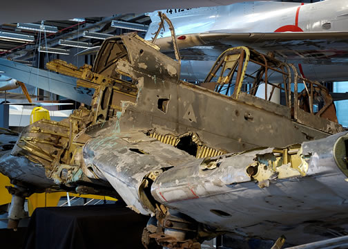
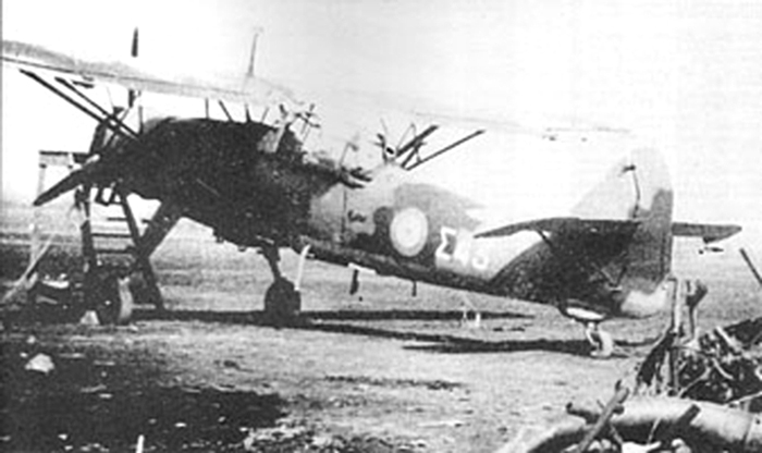
The German forces advancing into Greece in April 1941 found a damaged Henschel Hs 126 coded Σ (Sigma) 43 on an abandoned Greek airfield. Obviously this or any other Greek Henschel was never used by the Luftwaffe
Layout